
 Sign In

 Shop
Shop

 Academy
MacBook Pro 2017 Won't Turn On Troubleshooting Guide
As the latest MacBook model in 2017, Macbook Pro 13" (A1708) is different from previous models in exterior design and interior logic board circuit construction. Which also increases difficulty of its repairability - it scored a 2 out of 10 on ifixit repairability scale (10 is the easiest to repair). This time we will share with you a complex MacBook won’t turn on repair case caused by multiple faulty components like capacitors, inductors, etc..
Problem
Press power button, and the MacBook won’t turn on. Confirm the serial number on the lower case first. Pop free the clips securing the lower case to the chassis. Pull the lower case away from the hinge area to separate. Then remove the lower case.
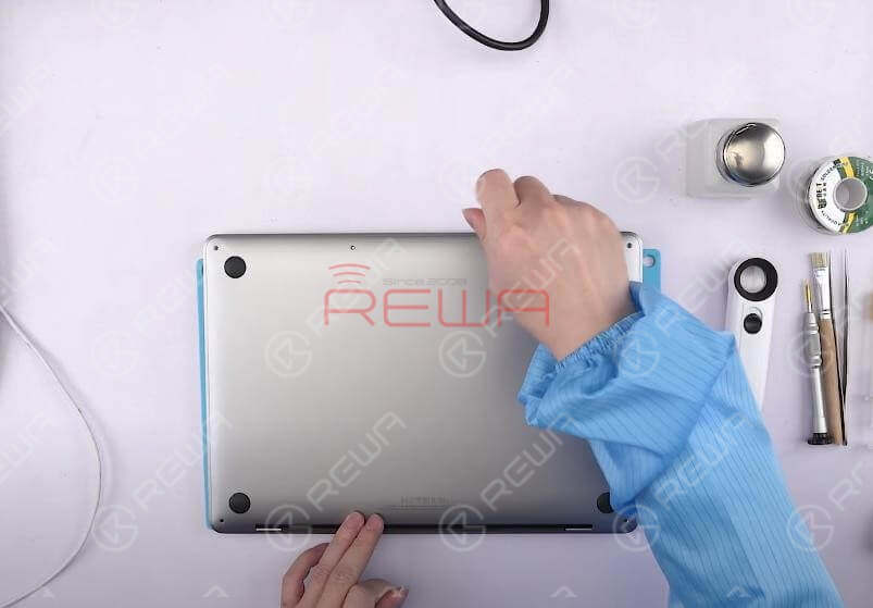
Disconnect the battery and detach the logic board. Remove the SSD module. Then confirm the board number of logic board.
Diagnosis
Run diode mode measurement of main power supply inductor L7030. The measured value is 348, which is normal. Switch to voltage mode. Plug in AC adapter and measure the voltage of L7030. The measured voltage value is 0V, which is abnormal. Normal voltage value should be around 13V. 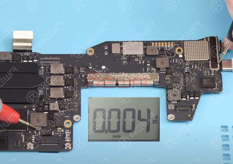
Roll out the maintenance drawing and bitmap. Confirm L7030 relevant circuit PPDCIN_G3H (also known as =PPHV_EXT_G3H). 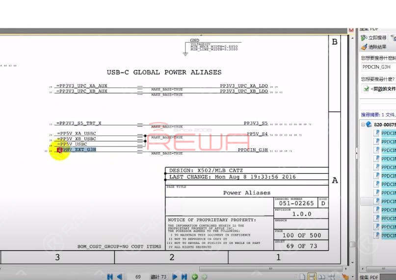
Confirm the working condition of U3100. Confirm U3100 main power supply Pin H1 VIN_3V3 (also known as =PP3V3_G3H_UPC_XA). =PP3V3_G3H_UPC_XA is converted into PP3V3_G3H via R3000.
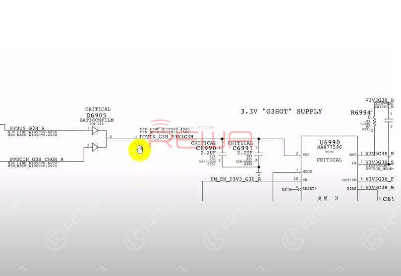
Then confirm the power supply source of PP3V3_G3H. PP3V3_G3H is outputted from U6990 via L6995. Locate U6990 with bitmap. Then locate the corresponding position of U6990 on the logic board. Traces of damage can be found on chips around U6990. Confirm the working condition circuit of U6990 with drawing. Then locate L6995 with bitmap.
Switch to diode mode and run diode mode measurement of L6995. The measured value is 342, which is normal. Roll out the drawing and locate the Pin 2 SUP of U6990 main power supply (also known as PPVIN_G3H_P3V3G3H). PPVIN_G3H_P3V3G3H is converted from compound diode D6905. Locate D6905 with bitmap. Then locate the corresponding position of D6905 on the logic board. 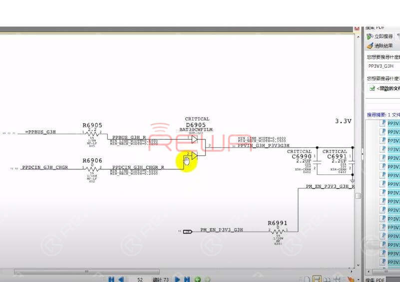
Run diode mode measurement of D6905 Pin 3. The measured value is 0, which indicates short-circuited condition. Run diode mode measurement of D6905 Pin 1. The measured value is 98, which is lower than normal value. Run diode mode measurement of D6905 Pin 2. The measured value is 526, which is normal. 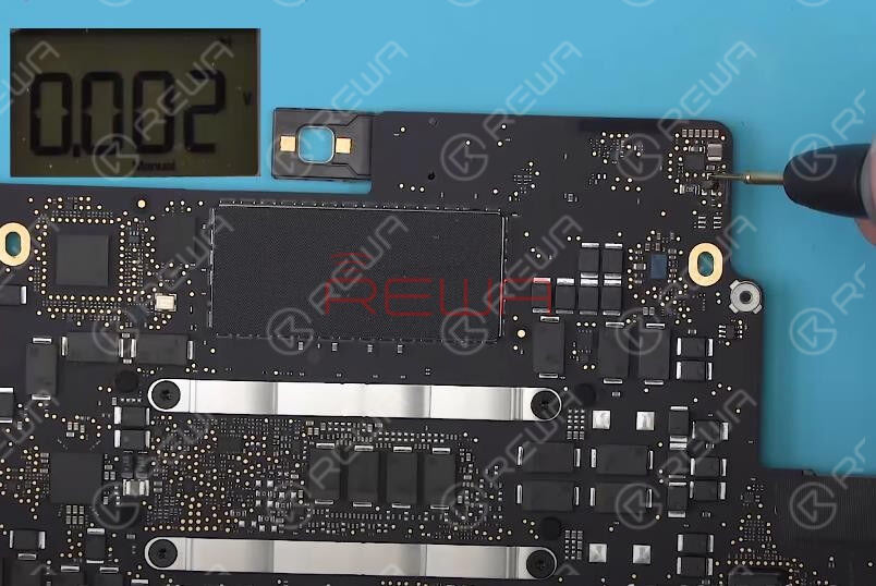
We can conclude that D6905 has been damaged.
Troubleshooting
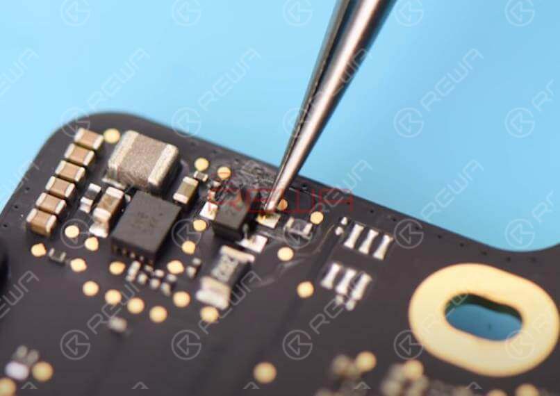
Let’s detach D6905 first. Apply some BGA Paste Flux and detach D6905 with Hot Air Gun at 430℃. Clean with PCB Cleaner after the logic board has cooled enough. 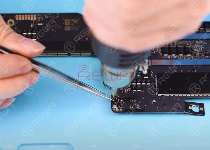
Run diode mode measurement of the D6905 detached bonding pad. The measured value of Pin 1 is 444, which is normal. The measured value of Pin 3 is 0, which indicates short-circuited condition. Confirm relevant circuit of D6905 Pin 3 power supply with drawing. The circuit consists of U6990, C6990 and C6991. Detach U6990 to check if the short-circuited condition can be solved.
Apply some BGA Paste Flux and detach U6990 with Hot Air Gun at 430℃. Clean with PCB Cleaner after the logic board has cooled enough. 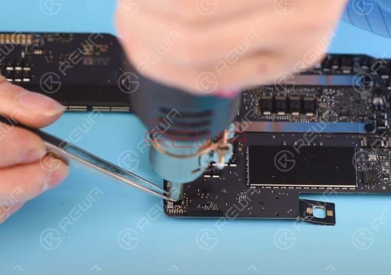
Run diode mode measurement of D6905 Pin 3 again. The measured value is 0, which indicates short-circuited condition. We can conclude that the faulty condition has nothing to do with U6990. Yet U6990 might has been damaged as well. The faulty condition might be related to C6990 and C6991.
Detach C6990 first. Apply some BGA Paste Flux and detach C6990 with Hot Air Gun at 430℃. Clean with PCB Cleaner after the logic board has cooled enough. 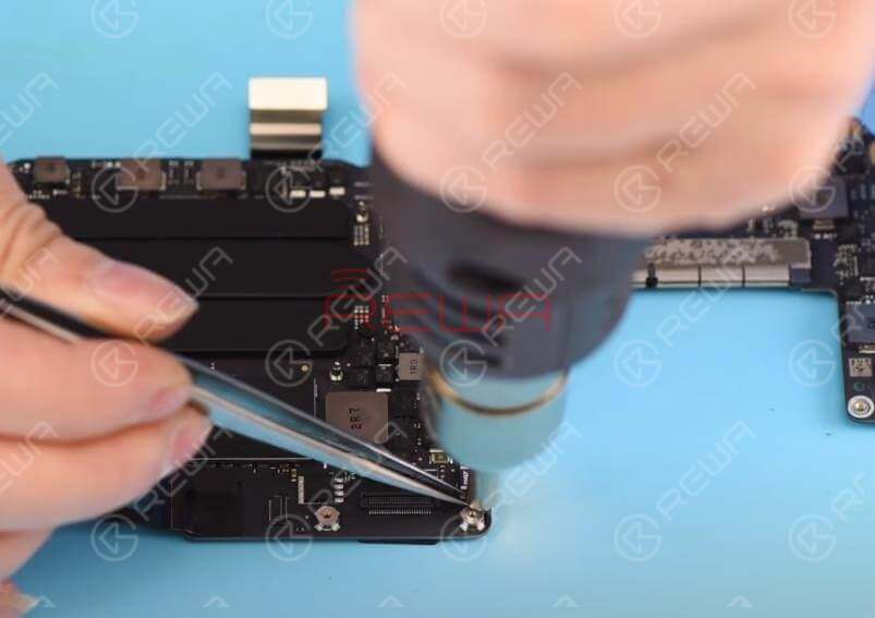
Then run diode mode measurement of D6905 Pin 3 again. The measured value is 593, which is normal. We can conclude now that the faulty condition is related to C6990. Also, we need to replace with a new U6990. Let's start with U6990 replacement. 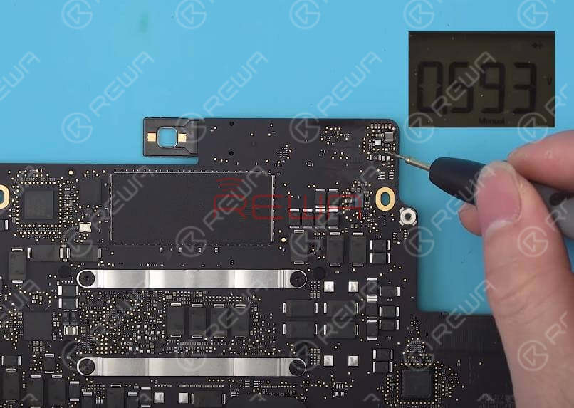
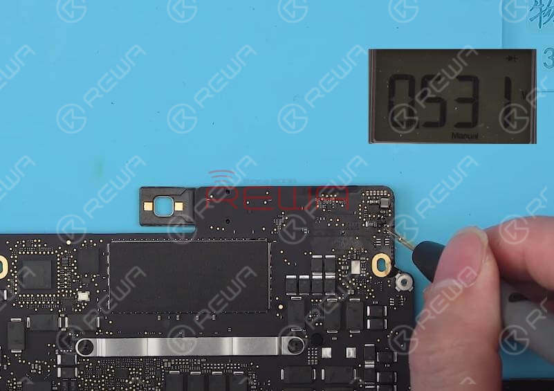
Apply some BGA Paste Flux and solder with Hot Air Gun at 430℃. Clean with PCB Cleaner after the logic board has cooled enough. Then run diode mode measurement of D6905 Pin 3 again. The measured value is 531, which is normal.
Next thing we do is to solder a new D6905. Apply some BGA Paste Flux and solder with Hot Air Gun at 430℃. For better soldering, add some low-melting point tins during the soldering process. Clean with PCB Cleaner after the logic board has cooled enough.
Then run diode mode measurement of three pins on D6905 one by one. The measured value of Pin 1 is 437, which is normal. The measured value of Pin 3 is 533, which is normal. The measured value of Pin 2 is 531, which is normal.
Next thing we do is to solder a new C6990. Apply some BGA Paste Flux and solder with Hot Air Gun at 430℃. Run diode mode measurement of D6905 Pin 3 again. The measured value is 533, which is normal.
Plug in AC adapter and measure the voltage of D6905 Pin 3. The measured voltage value is 19V7, which is normal. Then measure the voltage of L6995. The measured voltage value is 3V4, which is normal. Measure the voltage of L7030. The measured voltage value is 13V, which is normal. 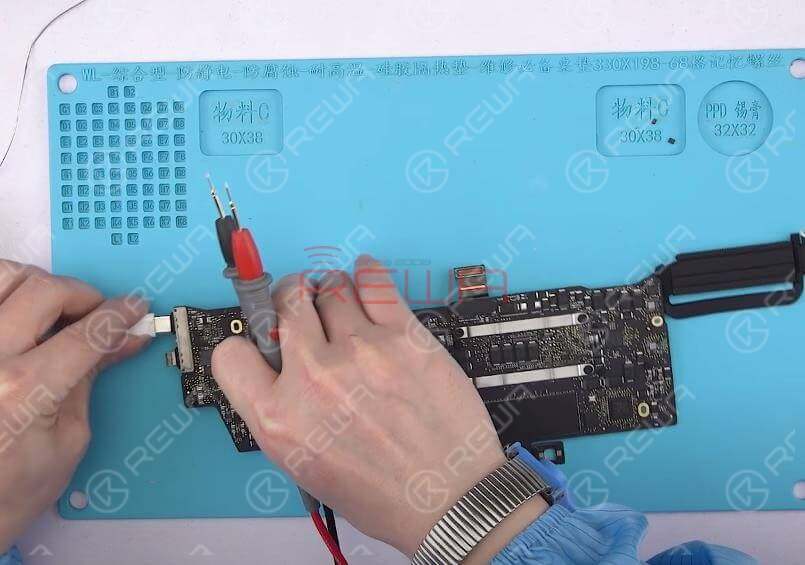
Measure the voltage of U3100 main power supply Pin H11 VBUS (also known as =PP20V_USBC_XA_VBUS). The corresponding measuring point is C3101. The voltage rises from 5V1 to 20V, which is normal. Then measure the voltage of logic board power supply group by group. All going well.
Reassemble And Test
Get the logic board mounted. Plug in AC adapter and power on. The MacBook turns on normally.Disconnect the power supply and insert the SSD. Plug in AC adapter and power on. The MacBook turns on normally.
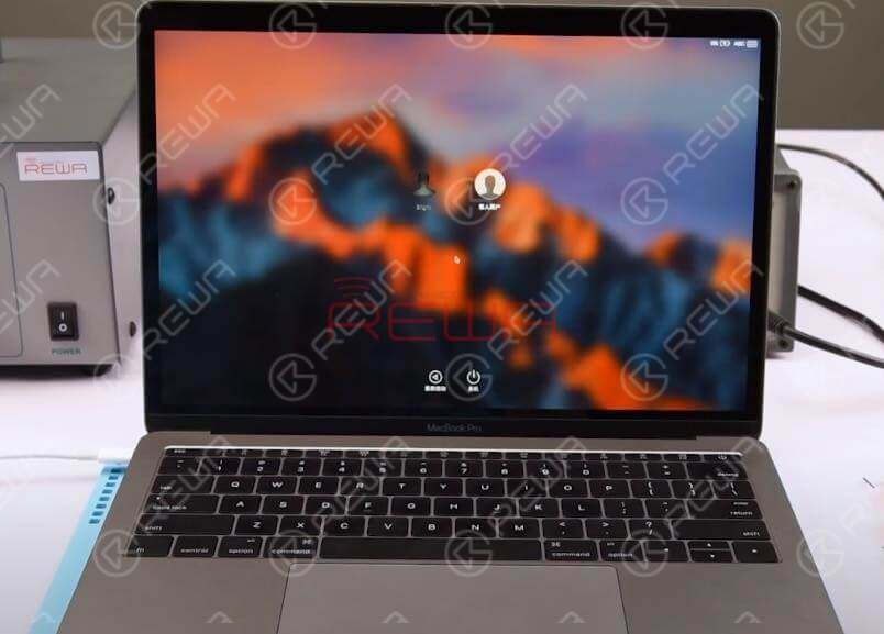
Disconnect the power supply and get the MacBook full assembled. Plug in AC adapter and power on. The MacBook turns on normally. Fault cleared.
For detailed operation about MacBook Pro repair, you can also check out REWA YouTube Channel .
More repair guides for MacBook repair:
Unlock MacBook 2015-2017 No Chip Removal
MacBook Air Won’t Turn On Troubleshooting
5 Minutes Done – MacBook No Display Repair
For MacBook spare parts , please visit REWA online shop .
For MacBook Repair Service, click here .
For the free schematics software used, go to REFOX .
REWA Academy
Developed by REWA Technology, REWA Academy is a platform that provides repair technique learning, practical demonstration, and idea-sharing for practitioners in the electronic repair industry. Over the years, our teaching staff and R&D team have dedicated themselves to developing systematic repair training courses online and offline.
You can also click the course link below to know more!
iPhone X Series Logic Board Repair Course
iPhone Logic Board Repair Foundation Course
iPhone Logic Board Repair Handwork Course
iPhone Logic Board Repair Work Flow & Troubleshooting Course
iPhone Logic Board Repair Cases Course


No Comments
0
1
Share
Apr 23, 2021
ABOUT REWA
REWA is a world leading electronics repair business solutions provider who was founded in 2008 in HongKong. We are committed to delivering one-stop services covering Sourcing Solution, Technical Support Solution as well as Recycle & Resell Solution.


