
 Sign In

 Shop
Shop

 Academy
MacBook Air 2015 No Backlight Repair
Typically with MacBook Air no backlight problem, the first thing to check is the backlight IC. However, this time we are treating one repair case that is much more complicated. The No Backlight issue is caused by damage of booster diode. Check our blog and see how we confirm the fault by measurement and diagnosis.
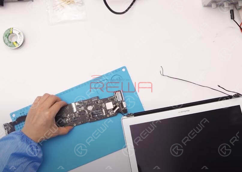
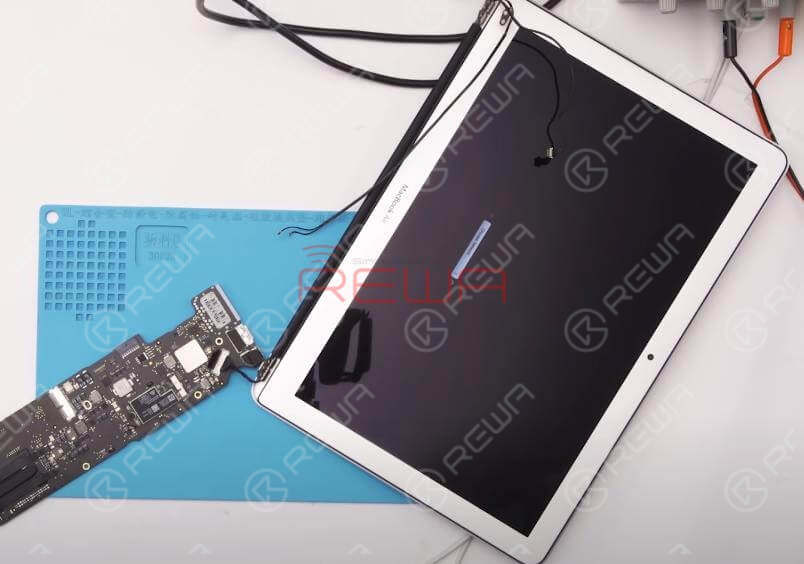
Disassemble MacBook
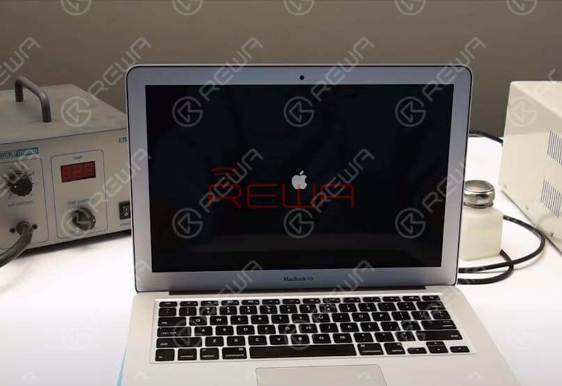
Power on. MacBook goes with dark screen. User login interface can be dimly seen.
Remove the lower case and disconnect the battery. Remove the SSD module. Detach the logic board. Detach IO Board as well. Then connect the IO board to the logic board. Confirm the board number of logic board. Detach the display. Then connect the display with logic board. Switch the Multimeter to diode mode. Roll out the maintenance drawing and bitmap.
Run Measurement
Locate LCD connector J8300. Check PPHV_S0SW_LCDBKLT. Check relevant circuit of PPHV_S0SW_LCDBKLT. Locate inductor L7701 with maintenance drawing. Measure resistance of L7701. Measured resistance value is 414, normal value. 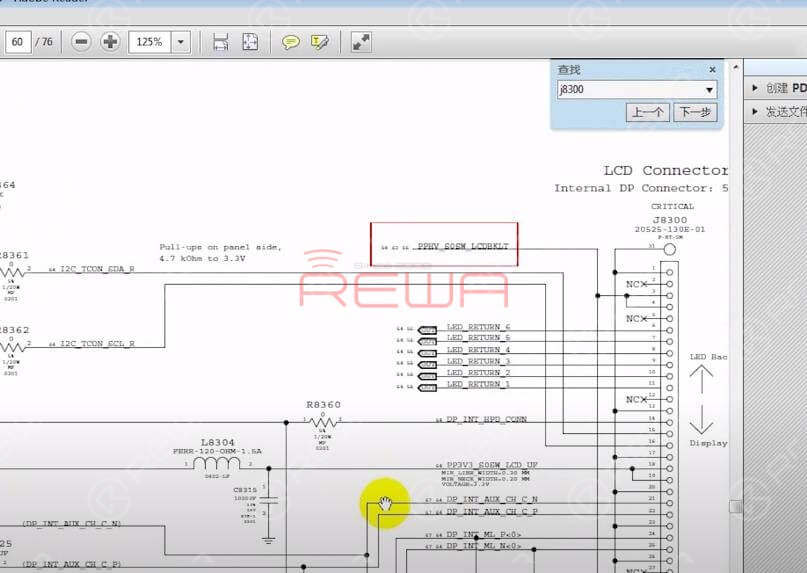
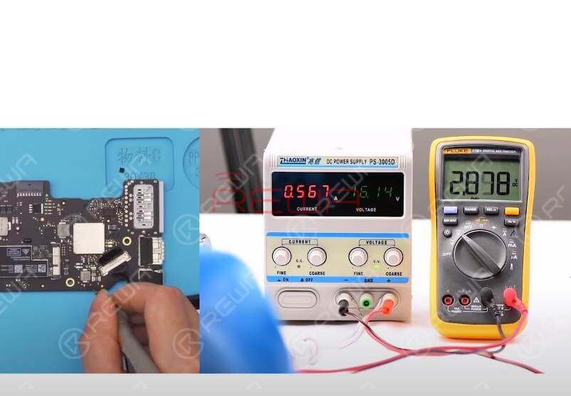
Switch to voltage mode. Plug in AC adapter and measure the voltage of L7701. The measured voltage value is 8V5. Abnormal voltage value. Normal voltage value should be 25V or so.
Disconnect the power supply. Disconnect the display from logic board. Roll out the drawing and confirm the working condition of IC U7701. Locate IC U7701 with bitmap. Locate capacitor C7710 with bitmap. C7710 is connected with U7710 power supply VIN Pin. 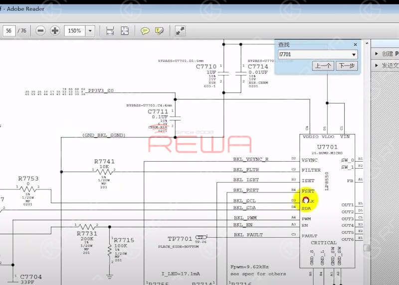
Switch to resistance mode. Measure the resistance of C7710. Measured resistance value is 428, normal value. Switch to voltage mode. Plug in AC adapter and measure the voltage of C7710. The measured voltage value is 5V, normal value.
Locate C7711 with bitmap. C7711 is connected with VDDIO Pin. Measure the voltage of C7711. The measured voltage value is 3V3, normal value. Confirm EN Pins of U7701 with maintenance drawing. Locate R7731 and R7715 with bitmap.
Warm tips: voltage of EN Pins can be measured with display connected.
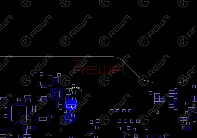
Connect the display with logic board. Plug in AC adapter and measure the voltage of R7731. Voltage value of first Pin is 8V5, second Pin 2V8. Normal value.
Warm tips: voltage value of EN Pins can be read on the meter with display on.
Confirm PWM Pin of U7701 with maintenance drawing. Locate R7704 with bitmap. Measure the voltage of R7704. The measured voltage value is 3V3, normal value.
Confirm SCLK Pin of U7701 with maintenance drawing. Locate R7753 with bitmap. Measure the voltage of R7753. The measured voltage value is 3V3, normal value.
Confirm SDA Pin of U7701 with maintenance drawing. Locate R7757 with bitmap. Measure the voltage of R7757. The measured voltage value is 3V3, normal value.
Preliminary judgement - U7701 broke down
Replace U7701
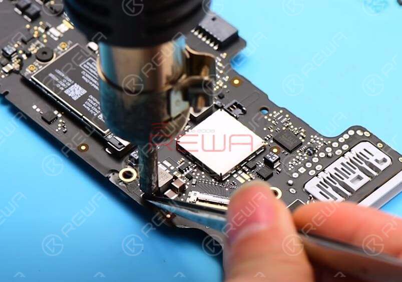
Disconnect the power supply. Reballing the new U7701 first. Take down the damaged U7701. Then replace with the new U7701. Solder with Hot Air Gun at 430℃.
Wait for the logic board to cool for 5 minutes. Confirm if soldering work has been completed perfectly with Magnifier. Clean with PCB Cleaner.Plug in AC adapter and test if the fault has been cleared. The fault hasn’t been cleared with IC replaced.
Replace D7701
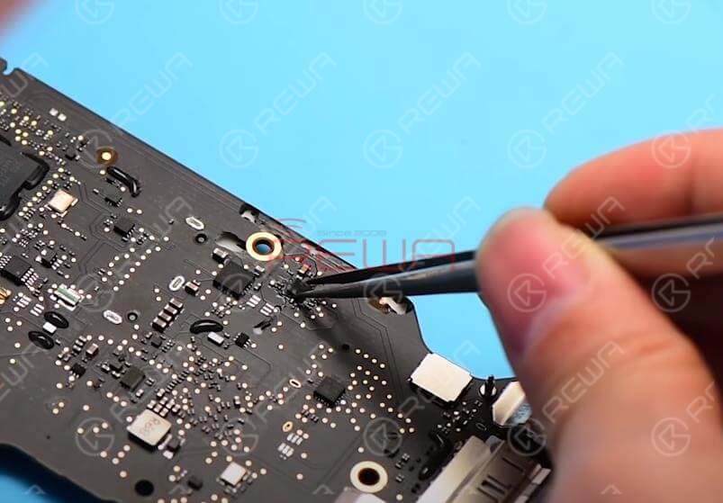
Connect the display with logic board. Confirm the relevant circuit of PPHV_S0SW_LCDBKLT with drawing. Locate booster diode D7701 with bitmap. Plug in AC adapter and measure voltage at two ends of D7701. Measured voltage value of End A is 8V5, End K 2V9. Abnormal voltage value for End K. Normal value should be 25V or so.
Disconnect the power supply. Disconnect the display from logic board. Switch to diode mode. Measure resistance at Positive&Negative ends of D7701. Forward direction reads ‘OL’ on the meter, infinite value. Opposite direction reads 176 on the meter. Abnormal resistance value for D7701. We need to replace with a new D7701.
.
Once replacing has been finished, wait for the logic board to cool for 5 minutes. Clean with PCB Cleaner. Measure resistance of the new D7701. Forward direction reads 166, normal value. Opposite direction reads ‘OL’ on the meter, normal value.
Measure the resistance between D7701 and grounding. Measured value of End A is 388, End K 531. Normal value for the two ends.
Test
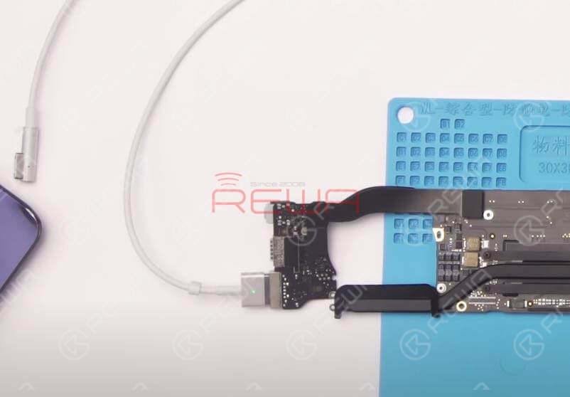
Connect the display with logic board and test again.
Tips: connect with an external USB keyboard, press ‘Alt’ button to power on.
The screen lights up. Switch to voltage mode. Measure voltage at two ends of D7701 again. Measured voltage value of End A is 8V5, End K 25V. Normal value for the two ends.
Reassemble And Test
Disconnect the power supply. Get the screen installed. Get the logic board mounted. Insert the SSD. Plug in AC adapter and test. MacBook goes with normal display.
Disconnect the power supply and power off. Get the MacBook full assembled. Run keyboard test and touch test. Repairing completed successfully.
For detailed operation about MacBook repair, you can also check out REWA YouTube Channel .
More repair guides for MacBook repair:
Unlock MacBook 2015-2017 No Chip Removal
MacBook Air Won’t Turn On Troubleshooting
5 Minutes Done – MacBook No Display Repair
For MacBook spare parts , please visit REWA online shop .
For MacBook Repair Service, click here .
For the free schematics software used, go to REFOX .
REWA Academy
Developed by REWA Technology, REWA Academy is a platform that provides repair technique learning, practical demonstration, and idea-sharing for practitioners in the electronic repair industry. Over the years, our teaching staff and R&D team have dedicated themselves to developing systematic repair training courses online and offline.
You can also click the course link below to know more!
iPhone X Series Logic Board Repair Course
iPhone Logic Board Repair Foundation Course
iPhone Logic Board Repair Handwork Course
iPhone Logic Board Repair Work Flow & Troubleshooting Course
iPhone Logic Board Repair Cases Course


No Comments
0
0
Share
Apr 23, 2021
ABOUT REWA
REWA is a world leading electronics repair business solutions provider who was founded in 2008 in HongKong. We are committed to delivering one-stop services covering Sourcing Solution, Technical Support Solution as well as Recycle & Resell Solution.


