
 Sign In

 Shop
Shop

 Academy
How To Fix iPhone Black Camera - Jumping Wire Applied
iPhone front camera not working? What should a repair technician start with? Follow our repair guide today and learn how to troubleshoot step by step. What’s more, REWA LAB will show you how to avoid further damaging the logic board by adopting a fresh new repair solution. Check it out now!
Test
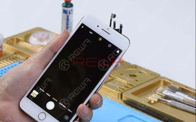
Run cosmetic inspection of the logic board. The logic board is not deformed or water damaged. Now, let’s get the logic board and cameras installed. Get the iPhone display assembly installed and battery connected.
Press power button to power on. Tap ‘Camera’ icon and enter into camera mode. The rear camera works normally. Switch to front camera. It can not be activated.
Diagnosis
Let’s check front camera connector J4503 and relevant circuits first. Run diode mode measurement of pins on J4503. The measured value is normal. (In this step, you need a bitmap software that provides reliable schematics and board files for motherboard repair. REWA used Refox in the video.)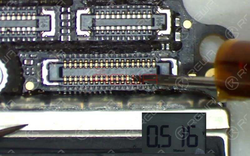
Next, we need to measure working voltage of the front camera.Get the two cameras installed. Connect the logic board with the display assembly. Connect battery connector with the Power Supplier. Press ON/OFF button on the Power Supplier to get the logic board power supplied. Then press power button on the Power Supplier. The system will then detect power button press.
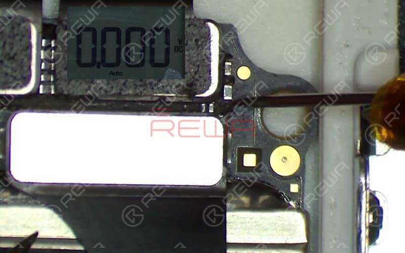
Tap ‘Camera’ icon to enter into camera mode. Run voltage mode measurement of front camera power supply test points FL2901 and C2909. The measured value of FL2901 is normal. There is no voltage measured on C2909, which is abnormal. Normal voltage should be 2.9V.Outputted from Pin G10 of U1801, the 2.9V voltage reaches Pin 1 of J4503 by way of FL2903, C2909, C2904 and C2901.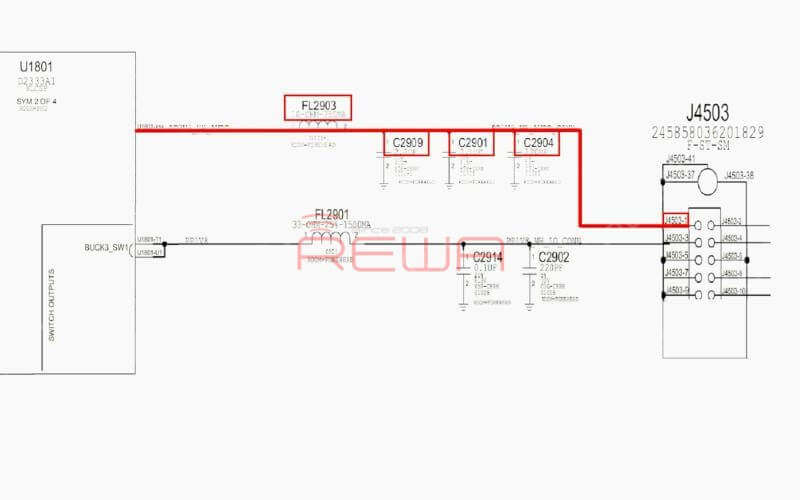
Continue to run diode mode measurement of FL2903. Judging by the measured value, FL2903 is in normal status. We can confirm now that the fault is related to U1801.
Troubleshooting
We can fix it by replacing with a new U1801 or borrow 3V voltage from other points on the board. Since U1801 is located on the backside of CPU and replacing process can cause pseudo soldering of CPU, here we will adopt the voltage borrowing way.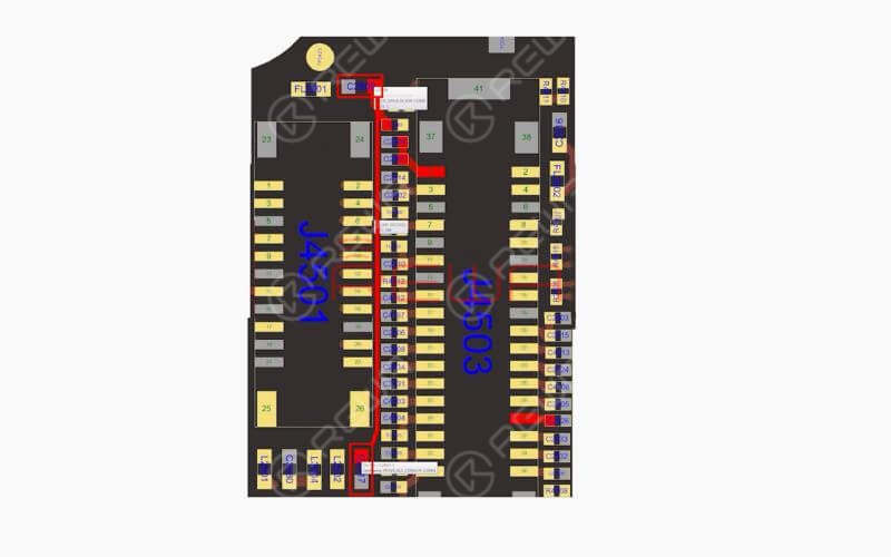
Here we need 0.1mm solder tinned enamelled wire. With one end of the wire soldered to C2917, a 3V voltage point nearby, solder the other end to C2909.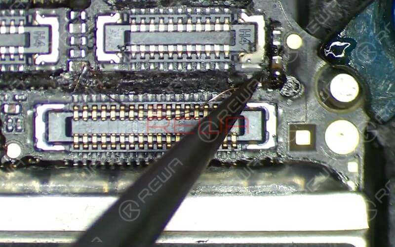
Once done, clean with PCB Cleaner. Apply some UV Curable Solder Mask to the soldered area. Then solidify the logic board under UV Dryer Lamp for 5 minutes.
Reassemble And Test
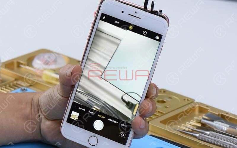
Next, we can assemble the phone and test. Tap ‘Camera’ icon to enter into camera mode. The front camera works normally. Switch to rear camera. The rear camera works normally. Fault cleared.
Tools & Parts Needed
Integrated Mobile Phone Repair Platform
iPower Max Power Supply iPhone Disassembling Tool Kits
You can also visit REWA YouTube Channel to check our video and learn how to fix iPhone black camera in a safe way.
0
0


No Comments
0
0
Share
Apr 23, 2021
ABOUT REWA
REWA is a world leading electronics repair business solutions provider who was founded in 2008 in HongKong. We are committed to delivering one-stop services covering Sourcing Solution, Technical Support Solution as well as Recycle & Resell Solution.


