
 Sign In

 Shop
Shop

 Academy
How to Fix iPhone 11 Pro Max No Service Issue
Recently, many repair technicians reported that they had received lots of iPhone 11 Pro Max with no service. Worse still, the fault could not be eliminated after replacing the signal board. Based on experience, REWA LAB technicians preliminarily conclude that the fault is likely on the signal pads of the logic board. Let’s check it out!
Step 1: Fault analysis
The motherboard has been repaired once. The original fault was no service but with the baseband modem firmware. The previous repair welded the baseband CPU and baseband EPROM to a good signal board. But the phone still had no service. It can be preliminarily judged that there are two possible faults. One is the damage of baseband CPU and baseband EPROM. The other is the damage of circuits related to the signal on the logic board.
First of all, we install the motherboard on the phone to test. The phone turns on normally but has no service.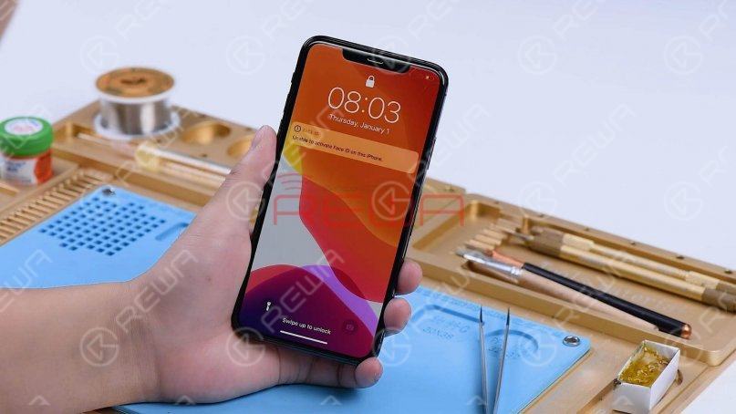
Go to Settings, General, and About. We can see that the phone has no modem firmware.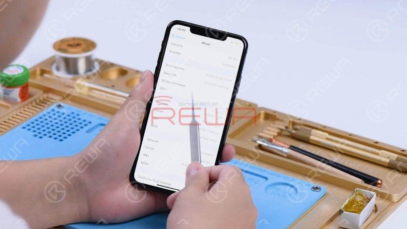
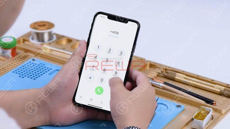
Dial *#06# and the IMEI can’t be seen.
The phone used to have modem firmware but now no longer has it. The cause may be related to pseudo soldering of the motherboard middle layer or damage of the baseband CPU and baseband EPROM.
Step 2: Motherboard separation and troubleshooting
Then we separate the motherboard to locate the faulty component. Put the motherboard on the Heating Platform and set the temperature to 185℃.
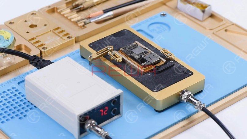
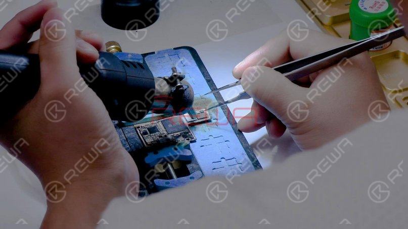
When the temperature has risen to 185℃, remove the logic board with tweezers.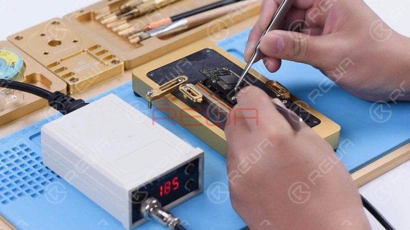
Turn the power off and remove the signal board.
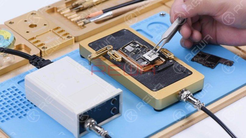
Clean the logic board with PCB Cleaner. Since the signal board has been replaced, we need to check the logic board first. According to the test result, we can later determine whether the baseband CPU and EPROM are damaged.
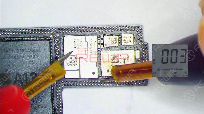
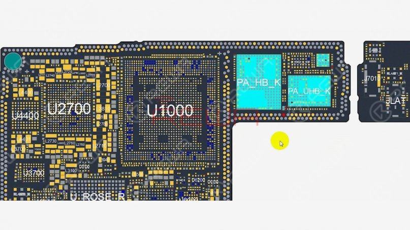
Run diode mode measurement of the signal pads on the middle layer of the logic board. When measuring pin 131, the diode value is 003. The normal value should be around 400.
Open the bitmap and many associated components are seen on the circuit.
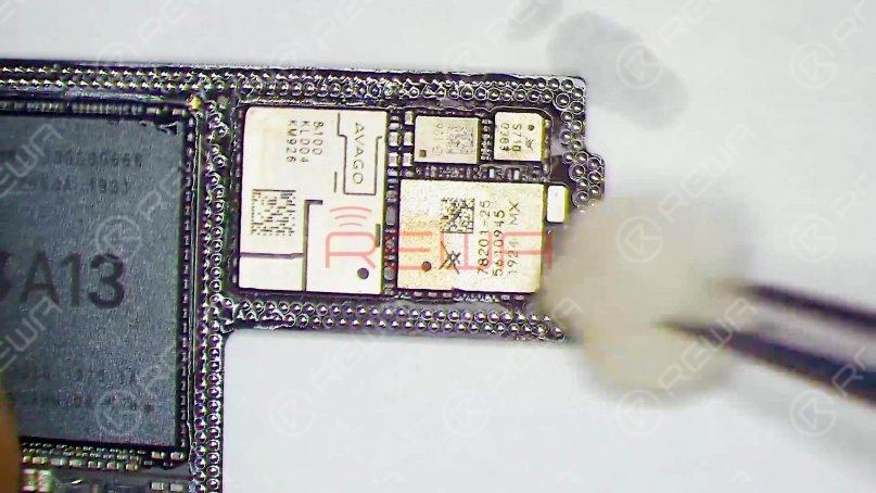
Then we locate the faulty component with rosin detecting. Dip rosin with Soldering Iron at 365℃ and smoke some rosin on associated components.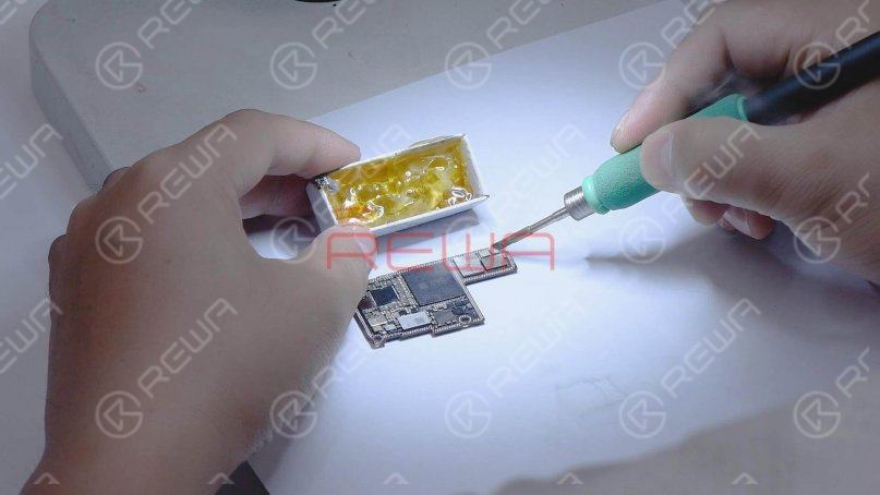
Set the direct current supply to 1.8V. Connect the positive and negative anode of the direct current supply with multimeter probes.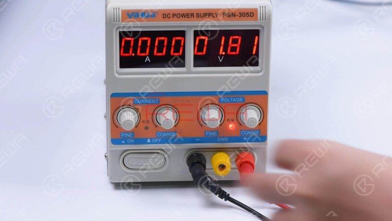
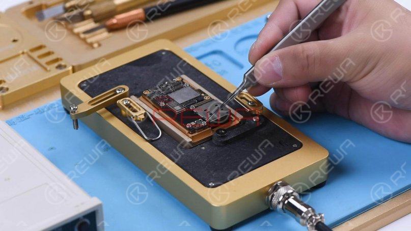
Then connect the black probe to the ground and connect the red probe to pin 113 on the logic board. We can see rosin on a capacitor has melted. It indicates that the component is damaged. This circuit has multiple filter capacitors, so we can directly remove the damaged capacitor.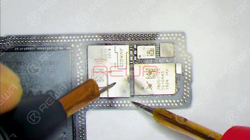
Remove the capacitor with Hot Air Gun at 350℃ and airflow 3.
Measure the logic board again after it has cooled. The diode value returns to a normal value of 458.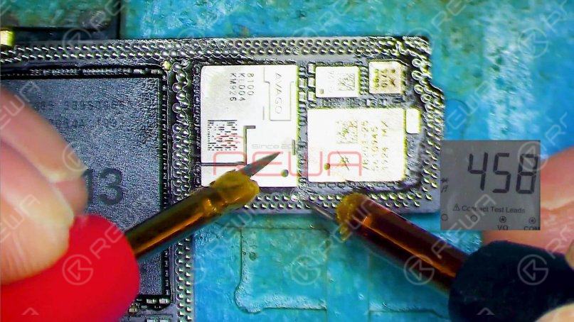
Step 3: Motherboard restoration
Next, we need to restore the motherboard. Firstly, we need to remove tin on the bonding pad of the motherboard. Smear rosin with Soldering Iron at 365℃ and solder-wick to remove tin on the bonding pad.
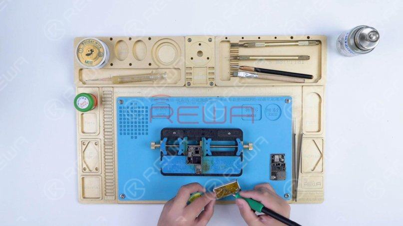
Remove tin on the signal board with the same method. After that, clean the logic board and signal board with PCB Cleaner.Next, attach the signal board to the Reballing Platform and put the Reballing Stencil in position. Apply a layer of medium-temperature Solder Paste evenly.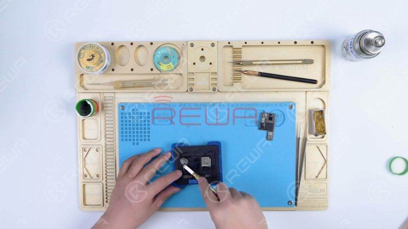
After reballing, put the signal board on the 185℃ Heating Platform to heat. When the solder balls are formed, turn the power off and cool the signal board.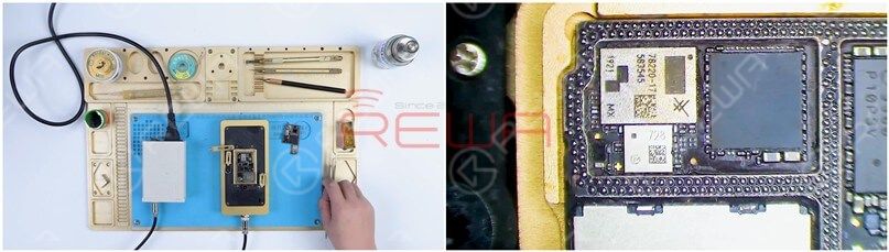
Apply some Paste Flux to the bonding pad of the signal board and align the logic board with the signal board.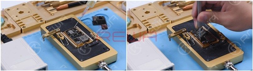
Keep heating the motherboard on the 185℃ Heating Platform. Push the logic board gently with tweezers and the logic board can return to the previous position. It shows that the motherboard has completed soldering.
Turn the power off and cool the motherboard for 5 minutes. Then remove the motherboard and install it on the phone. The phone turns on normally and the 4G signal can be received. A phone call can also be made. The fault is cleared.

Summary
The iPhone 11 Pro Max has been repaired once and still has no service after the baseband CPU and EPROM has been welded to a good signal board. It can be preliminarily judged that there are two possible faults. One is the damage of baseband CPU and baseband EPROM. The other is the damage of circuits related to the signal on the logic board. Through measuring the signal pads on the logic board and rosin detecting, a capacitor was found damaged. After removing the capacitor, the no service fault was cleared. We can rule out the possibility of baseband CPU and EPROM fault since the no service fault was eliminated after repairing the logic board.For more No Service content, please read the articles below.
Tips For iPhone 7 No Service Issue Troubleshooting
iPhone 6 No Service Hardware Fix Solution
If you want to study more, please feel free to visit our academy for repair courses.
0
0


No Comments
0
0
Share
Apr 23, 2021
ABOUT REWA
REWA is a world leading electronics repair business solutions provider who was founded in 2008 in HongKong. We are committed to delivering one-stop services covering Sourcing Solution, Technical Support Solution as well as Recycle & Resell Solution.


